The following data need to be provided to when placing an purchase to make sure the appropriate selection of the disc coupling:
Application and variety of duty
Style of driver (engine, motor, turbine, etc.)
Speed and horsepower
Style of driven
Shaft sizes and separation
Area limitations for big diameter and length
Form of match (Interference match default, clearance match and shaft locking device planning available upon request)
Particular demands (vertical mounting, drop out center, flange mount, electrically insulated, API-610 as much as three,800 RPM, shear pins, balancing, and so on.)
Angular misalignment, axial misalignment, and rated torque are all related towards the 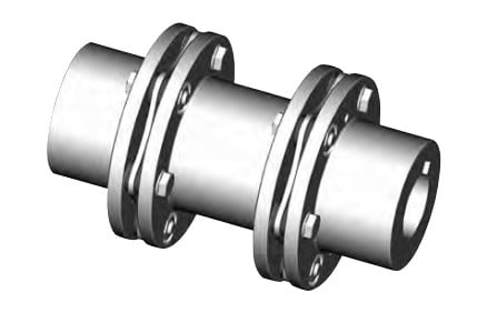 coupling’s capacity to accommodate application torque in excess of any time period of time. As illustrated while in the following charts, when the application torque increases to 50% on the coupling capability, the means of the coupling to accommodate angular misalignment to is lowered. Precisely the same holds correct for your capability to accommodate axial misalignment.
Selection Procedure
one. Select the coupling sort.
two. Select the driven machine services element SFA
3. Select the driving machine services issue SFD
Care must be taken when the driving machine is besides a normal electrical motor or turbine. Some engines will impose additional fluctuations on the drive system and allowance ought to be created accordingly. A torsional coupling may perhaps be needed for diesel drives.
Recommended Info Essential to Specify a Disc Coupling
Tags: